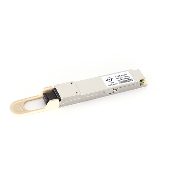
The optical transmitter portion of the transceiver incorporates a 4-channel VCSEL (Vertical Cavity Surface Emitting Laser) array, a 4-channel input buffer and laser driver, diagnostic monitors, control and bias blocks. For module control, the control interface incorporates a Two Wire Serial interface of clock and data signals. Diagnostic monitors for VCSEL bias, module temperature, transmitted optical power,received optical power and supply voltage are implemented and results are available through the TWS interface. Alarm and warning thresholds are established for the monitored attributes. Flags are set and interrupts generated when the attributes are outside the thresholds. Flags are also set and interrupts generated for loss of input signal (LOS) and transmitter fault conditions. All flags are latched and will remain set even if the condition initiating the latch clears and operation resumes. All interrupts can be masked and flags are reset by reading the appropriate flag register. The optical output will squelch for loss of input signal unless squelch is disabled. Fault detection or channel deactivation through the TWS interface will disable the channel. Status, alarm/warning and fault information are available via the TWS interface.

The optical transmitter portion of the transceiver incorporates a 4-channel VCSEL (Vertical Cavity Surface Emitting Laser) array, a 4-channel input buffer and laser driver, diagnostic monitors, control and bias blocks. For module control, the control interface incorporates a Two Wire Serial interface of clock and data signals. Diagnostic monitors for VCSEL bias, module temperature, transmitted optical power,received optical power and supply voltage are implemented and results are available through the TWS interface. Alarm and warning thresholds are established for the monitored attributes. Flags are set and interrupts generated when the attributes are outside the thresholds. Flags are also set and interrupts generated for loss of input signal (LOS) and transmitter fault conditions. All flags are latched and will remain set even if the condition initiating the latch clears and operation resumes. All interrupts can be masked and flags are reset by reading the appropriate flag register. The optical output will squelch for loss of input signal unless squelch is disabled. Fault detection or channel deactivation through the TWS interface will disable the channel. Status, alarm/warning and fault information are available via the TWS interface.